Sabtu, 23 Agustus 2008

KIT CYLINDERS


KIT CYLINDERS
We have included a cylinder from Parker-Hannifin Manufacturing. It is included in the kit for you to get started and understand pneumatics. Hopefully, you will find a use for it on your robot. will not work with this cylinder, as it has no magnetic piston.

Tubing

TUBING
Freelin-Wade has donated the tubing this year. Coiled tubing was also added this year.

QUICK CONNECT FITTINGS


QUICK CONNECT FITTINGS
SMC Pneumatics donated the quick connect fittings. These are really easy to use. All you have to do is push the tube into the fitting. Make sure you push the tubing all the way into the fitting. To release the tubing, just push on the release button and then pull the tubing out. Don’t attempt to pull the tubing without first pushing the release button. The picture below shows a representative example of these fittings but does not include all the ones in the kit.

Brass Fittings


BRASS FITTINGS
Parker Hannifin donated all the brass fittings. These are useful where you want to plug a port or plumb from one size port to another. It is important to note that all male threads require Teflon tape to seal properly. Wrap the tape around the fitting, leaving the first two threads free of tape This is because the threads are tapered and the tape may come loose from the first thread or so and clog up one of your valves. Parker Hannifin donated all the brass fittings. These are useful where you want to plug a port or plumb from one size port to another. It is important to note that all male threads require Teflon tape to seal properly. Wrap the tape around the fitting, leaving the first two threads free of tape This is because the threads are tapered and the tape may come loose from the first thread or so and clog up one of your valves.

Plug Valve


PLUG VALVE
Parker Hannifin donated the plug valve. This valve can be used to release all the air in the system.

Flow Control


FLOW CONTROLS
We have flow controls donated by SMC Pneumatics. The purpose of a flow control is to control the speed of the cylinder when it is extending or retracting. Always mount these into the ports of the cylinders before you hook up the tubing. Warning: Even if flow controls are used or the needle is turned out counter clockwise, the cylinder can extend very quickly. Always stay clear of any cylinder in motion.

Selenoid Valve

Bosch-Rexroth has also provided us with a single solenoid valve. The fittings allow you to push on the tubing and then tighten down on the tubing with the nut. The pressure port is shown on the top of the valve 6 and marked “P”. Flow comes out the “B” port and switches to the “A” port when the coil is energized. A solenoid connector plug is provided to wire the solenoid. The yellow arm on the opposite side of the valve is the manual override. On this valve you can turn the override on and leave it in that position for testing. Note there is no nut on the “R” port, which is the exhaust port. Please remove the Black nuts which are for metric tubing and use the Gray nuts which are included. If you lose a gray nut, drill ¼” hole in one of the black nuts to use instead.

Electric Valve


FESTO has also supplied two single solenoid valves. In order to wire the valves you must remove the white plastic pin protector that comes over the pins. Instructions in the package explain how to wire the valve. The fittings are the push to connect type so all you have to do is push in the tubing. The blue manual-override switch closes the valve for testing, but is spring-loaded and will not maintain the valve's position when released.

ELECTRIC VALVES

ELECTRIC VALVES
SMC
has provided two double solenoid valves. If you pulse one of the solenoids to make the cylinder extend, you must then pulse the opposite solenoid to make it retract. Either solenoid may be left in the energized state. This is a great valve to use to maintain position when the power is turned off at the end of the match. If you use a single solenoid valve and the power is turned off, the valve would shift back to its original position and the cylinder will retract. A double solenoid valve will maintain its position until you turn on the opposite solenoid. The orange buttons on the top of the valves are manual overrides. With a double solenoid valve you can depress the override and the valve will shift and stay in that position. The valve is pilot operated and requires a minimum pressure of 20 psi to work. The valve comes separate from the mounting block and must be assembled to it. There are 2 gaskets included. Use the one with holes for the mounting screws. Always avoid turning on both solenoids at the same time. While this won’t hurt the valve, you cannot be sure which way the spool will shift. There is also a 24vdc double solenoid valve included in the kit as a spare. Should you need to replace one of the 12V solenoid valves, just unscrew the 24V pilot valves from each end of the spare and swap the solenoid bodies. Remount the 12vdc pilot valves. Then remount the solenoid assembly back onto the sub base-mounting block.

REGULATORS

REGULATORS
Norgren has donated the primary pressure regulator. These are relieving regulators. Assume that you extend the cylinder or the apparatus the cylinder is attached to against a wall. Then push against the wall with your robot. That would increase the pressure in the cylinder. The increased pressure will relieve out of the regulator and the cylinder will slowly retract. This
regulator has a maximum output pressure of 60psi. This regulator must be placed in-line right after the tanks to limit the pressure to all working circuits to 60psi. It is adjustable and the outlet pressure may be reduced at your discretion. Look at the top of the regulator. You will note that one port extends out a little bit more than the others. It also has an arrow on it to denote the outlet of the regulator. The opposite port is the inlet. A pressure gauge may be placed in either of the other ports. You will have to plug the other gauge port with the enclosed hex plug.

Monnier has donated the secondary regulator, which has a yellow ring around it. This is also a relieving regulator. Its purpose is to allow you to have a reduced pressure leg, if needed. There is an arrow denoting the direction of flow. The gauge may be placed in either of the other ports. The Monnier bag provides you with plugs to put into the gauge ports.

Tanks

TANKS
We have two tanks from Clippard Instruments. They should be mounted right after the compressor, before the Norgren primary pressure regulator.

Pressure Switch

PRESSURE SWITCH

We have included a pressure switch manufactured by The Nason Company. These switches are normally closed. The switches will open at approximately 115psi and will not close again until the pressure drops to approximately 95psi. This will allow you to turn off the compressor once you are up to 115psi, saving power in the battery. It should be wired directly to the robot controller digital input bank with PWM type cable. No specific Digital Input Port is designated for the pressure switch. The Robot Controller must be programmed to react to the Input Port that is connected to the pressure switch The Robot Controller will activate the designated Spike Relay to turn the Compressor “on” and “off”. There is no default program in the Robot Controller to control the Compressor power. Do not put the pressure switch in series with the power supply to the compressor.

Jumat, 22 Agustus 2008

Compressor


COMPRESSOR
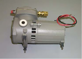
We have the same compressor provided by Thomas Industries that we’ve had over the last few years. The compressor will put out approximately 120psi before the relief valve opens. Because the compressor can produce a significant amount of vibration, we have included vibration isolation mounts donated by the Lord Corporation. They can be screwed directly into the feet of the compressor as shown on the following picture. In order for these to isolate the vibration, they need to be mounted to a stiff piece of metal such as a 1/4” aluminum plate. The distance between the front feet is 3.5”. The distance from the centerline of these feet to the rear foot is 5.19”. A spike relay should be used to control the power to the compressor using a 20amp breaker, not a fuse. Ensure that the relay is programmed to provide “forward” power only to the compressor. Do not reverse the compressor! Norgren has supplied the pressure relief valve. It is shown installed on the compressor.